
Yet another smart mirror
Created: 2023-01-22
- Introduction
- Supplies
- The "smart" in smart mirror
- Setting up a headless RPI
- Install the image to the SD card (CLI)
- Configure the RPI
- Configure SSH (Optional but very recommended)
- Installing a desktop manager
- Install and configure Magic Mirror
- Screen panel & controller
- Replacing the kit screen panel keyboard
- New flashy keyboard
- Integrating everything
- Reflections and future improvements
- Cold cathode fluorescent lamps (CCFL)
- One power cable instead of two
- An even more lightweight graphical environment
- Power off the display when no one is home
Introduction
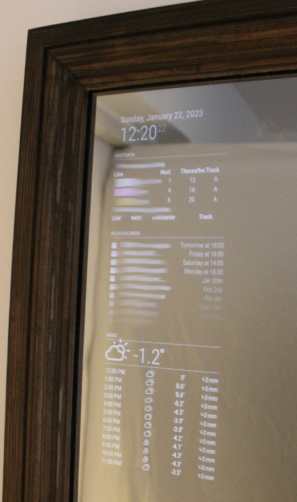
A smart mirror is essentially just a mirror with a display, electronics stuffed behind it and some software sprinkled on top. The main purpose is to display information in a condensed (hands-free) way while getting ready for the day. Mine is placed in the hallway to easily check the weather and if public transport is delayed before I go to work.
Consider this post more of a project summary rather than a build-step-by-step-writeup. For some time now I've wanted to build a smart mirror, after days of work spread out over maybe two or three years I have puzzled together something that I now finally can call a "smart" - using a Raspberry PI connected to a screen that is installed behind a one-way mirror. It is by no means an original idea. There are many YouTubers happy to tell you exactly how they made their mirror. Not to mention the multitudes of great blog post writeups out there.
The idea of building a smart mirror originally came to me either from a DIY perks video or from the office's smart mirror where I did my bachelor thesis. I can't remember which one came first. Both of those were acrylic mirrors. I decided to go with glass since I did not want a plastic-y looking mirror. My motivation to build my smart mirror came from the fact that I wanted to build something similar but of a slightly more luxurious and fancy design - something closer to furniture rather than an accessory. I did not realise beforehand how expensive and heavy that meant.. but that's another topic.
Supplies
Printables & 3D Printing
- 3D printer e.g. Prusa
- Big roll of PLA
Tools, Fixtures & Fittings:
- T20 (4x20mm) screws
- Digital voltmeter
- Solder iron & solder
- Cordless brushless drill driver 18V.. or a screwdriver
Hardware & Electronic Components
- Raspberry Pi 3B+ (RPI)
- LCD panel controller kit
- LCD panel (LM215WF1-TLB1)
- 12VDC 3A adapter
- 5VDC 2A adapter
- SD card
Keyboard side-project
- x6 mechanical switches
- 6 keycaps
Mirror materials (not part of this write-up)
- Ninja glass (a cool name for a two-way mirror)
- Wooden frame
The "smart" in smart mirror
I contemplated between writing my own smart mirror software or using Magic mirror. Since this project was already extensive enough with the frame woodworking I chose the latter.
Magic mirror is an open-source modular smart mirror platform with support for a lot of community-made modules that can easily be installed and configured. In the introduction, I mentioned that I want to check if public transport is delayed. Well, I didn't have to write any software to enable that. I just had to include and configure MMM-Vasttrafik-PublicTransport, which is a module to display public transport operated by Västtrafik for the western part of Sweden. My magic mirror configuration including all modules can be found here.
Setting up a headless RPI
Any OS might suffice for a smart mirror but I went for the officially supported Raspberry Pi OS for the RPI. I decided to use RPI OS lite which comes without a desktop pre-installed. Yes, a smart mirror needs to be able to display something on a screen using either a desktop or a standalone window manager ( also maybe more ways that I don't know about). But instead of using a fully-fledged gnome desktop we will install something more lightweight, LightDM.
There is an official tutorial on how to flash the image onto the sd card which can be found here those comfortable with using a CLI have written a quick step-by-step below on how to download and flash the RPI without having to connect a screen below.
There is also a community-driven magic mirror prepared image here which is raspios lite with preinstalled configurations and binaries. You just provide your wifi credentials in a file and after ~10min after the RPI has booted you have magic mirror up and running. This guide will however focus on configuring it all manually.
Install the image to the SD card (CLI)
# Run the following commands on your host computer
# with an sd card connected.

# Download Raspberry Pi OS Lite
$ curl -O https://downloads.raspberrypi.org/raspios_lite_armhf/images/raspios_lite_armhf-2022-09-26/2022-09-22-raspios-bullseye-armhf-lite.img.xz

# List block devices before connecting SD card
$ lsblk > block_devs_before

# Now connect the sd card and list block devices after
$ lsblk > block_devs_after

# Now check what block device is connected to the SD card
$ diff block_devs_before block_devs_after
17a18,19
> mmcblk1       179:24   0   7.5G  0 disk
> └─mmcblk1p1   179:25   0   7.4G  0 part

# Extract and flash img file to SD card
$ xzcat -d 2022-09-22-raspios-bullseye-armhf-lite.img.xz | sudo dd of=/dev/mmcblk1 bs=32M
Configure the RPI
...by editing the newly installed boot partition. Yes, there is no need to connect a keyboard and display to the RPI to configure. If you have followed the official tutorial on how to flash and configure the device, this section is probably not needed. There is a GUI where you can click setting boxes to enable stuff and also a prompt to create a user.
The following block of commands covers the configuration of:
- Creating a user
- Configure wifi
- Enable ssh
- Disable WLAN power save sleep
# To configure the headless device we need to still have the SD card
# plugged in.
# The boot partition needs to be mounted.
$ sudo mkdir /mnt/rpi-boot
$ sudo mount /dev/mmcblk1p1 /mnt/rpi-boot

# Create a user (userconf)
# Since default user pi is no longer added:
# https://www.raspberrypi.com/news/raspberry-pi-bullseye-update-april-2022/
$ echo -n "USERNAME" > userconf
$ echo "PASSWORD" | openssl passwd -6 -stdin >> userconf
$ sudo cp userconf /mnt/rpi-boot

# Enable ssh:
# Create an empty file labeled "ssh" or "ssh.txt"
$ sudo touch /mnt/rpi-boot/ssh

# Wifi settings (wpa_supplicant.conf):
# Create the file /mnt/rpi-boot/wpa_supplicant.conf with the following contents
$ echo "
country=SE # Replace this with your 2-digit country code
ctrl_interface=DIR=/var/run/wpa_supplicant GROUP=netdev
update_config=1
network={
    ssid="YOUR_NETWORK_NAME"
    psk="YOUR_PASSWORD"
}" > wpa_supplicant.conf
$ sudo cp wpa_supplicant.conf /mnt/rpi-boot

# ..and lastly when done unmount the SD card
$ sudo umount /mnt/rpi-boot

# Insert the SD card into the RPI and Power it up.
# Update the apt repositories and upgrade all packages
# and also disable wlan power save
$ ssh USERNAME@IP_ADDRESS "
sudo apt update; sudo apt upgrade; \
sudo iw wlan0 set power_save off
"
Configure SSH (Optional but very recommended)
This section covers how to configure SSH to not allow root or password logins only pub/priv key.
Add host public key to RPI allowed keys:
# First generate a ssh pub/priv keypair for yourself.
# (Nowadays Ed25519 is preferable over RSA so I'll use that)
$ ssh-keygen -t ed25519

# ..then generate a ssh pub/priv keypair for the RPI
$ ssh USERNAME@IP_ADDRESS "ssh-keygen -t ed25519"

# This will prompt the user to input PASSWORD.
# USERNAME and PASSWORD is the username selected in the previous section.
$ ssh USERNAME@IP_ADDRESS "echo `cat ~/.ssh/id_ed25519.pub` >> ~/.ssh/authorized_keys"
Then edit the ssh settings to not allow root or only allow pub key authentication /etc/ssh/sshd_config:
# Disable root login
PermitRootLogin no

# Enable public key authentication (add)
PubkeyAuthentication yes

# Disable tunneled clear text passwords
PasswordAuthentication no

# Change to yes to enable challenge-response passwords (beware issues with
# some PAM modules and threads)
ChallengeResponseAuthentication no
Installing a desktop manager
So now the headless RPI gets a head! I rolled the dice and chose a lightweight desktop manager called LightDM. There might be better alternatives to explore ( see future improvements).
What the desktop manager should be able to do:
- Auto start and login
- Auto-rotate to portrait orientation
- Start magic mirror GUI application
Install LightDM and X11 support to enable GUI applications to run on the RPI.
# xrandr from x11-xserver-utils is used to rotate the screen and select output source. See /etc/lightdm.conf below.
$ sudo apt install lightdm x11-xserver-utils
[Seat:*]
# Change rotation based on how your screen panel is installed
display-setup-script=xrandr --output HDMI-1 --rotate left

# Remember to replace USERNAME with actual username
autologin-user=USERNAME
Install and configure Magic Mirror
Run Magic Mirror on the RPI using this docker image (documentation can be found here). From the docs: "Using docker simplifies the setup by using the docker image instead of setting up the host with installing all the node.js stuff etc. Getting/Updating the image is done with one command.". The docker image can be run in two modes: server and electron. The server mode is useful e.g. when testing a new module before pushing it to the smart mirror or if you want to host your magic mirror application on a dedicated server. Electron mode is run on the target where your magic mirror display is connected. For this section, I will be using my magic mirror configuration. For this, I have some secret env files that I don't want to share. If you're interested in running my config anyways uncomment these lines:
env_file:
  - ./secret/secret.env
Github link to my magic mirror config
Server use case (docker-compose_mmserver.yml):
# Run this if you want to test my magic mirror configuration.
# This is how I tested my configuration on my laptop before trying to get
# it to work on my RPI
$ sudo apt install docker-compose
$ git clone git@github.com:kjeller/magicmirror_config.git
$ cd magicmirror_config

# If this step fails make sure to check that you are in the docker group.
$ ./start.sh server

# Now browse to localhost:8080 with any web browser
Electron use case (docker-compose_mmclient.yml):
# Run this on your RPI
$ sudo apt install docker-compose
$ git clone git@github.com:kjeller/magicmirror_config.git
$ cd magicmirror_config

# If this step fails make sure to check that you are in the docker group.
$ ./start.sh
After start.sh has been run magic mirror will automatically run on reboot and try to output to a display. The next step is to connect the RPI to a screen so that it actually can display stuff.
Screen panel & controller
But now for actually displaying stuff from the RPI to a screen.
I wanted it to be as cheap as possible while still being a viable option. I looked for alternatives on eBay but decided to go with an LCD panel I got from my friend (thanks Martin).
Replacing the kit screen panel keyboard
This is the screen panel controller keyboard that came with the kit that I bought specifically for my screen panel (you can find the link in the supplies section). As you can see it is not very aesthetically pleasing.
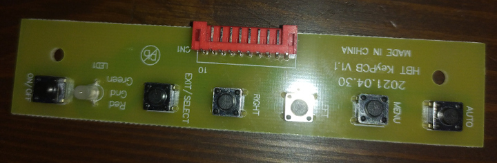
The mirror is not fully complete before I replace that ugly keyboard with something A) aesthetically pleasing B) smaller and C) with mechanical switches.
For starters, I had to trace the keyboard to see what pin each PCB switch is connected to including the RGB led. I used the diode tester function on my voltmeter and bleeped my way through all the traces, pin, test pads and whatnot which resulted in this basic schematic (thanks EasyEDA, I promise I will learn Kicad one of these days): 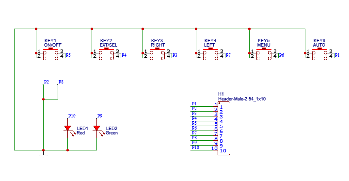
There's not much to reflect on here. The order in which the PCB switches appear does not in any way correspond to what order in which they are connected to the header pins. That doesn't matter much for this sub-project anyways. Also, notice that the RGB LED in the keyboard is a common cathode.
New flashy keyboard
Now for the design of the new flashy keyboard. For this step I kinda just took what I had laying around:
- Old Razer keyboard PCB full of green Razer RGB mechanical switches. Fun trivia: I ~~stole~~ found this in the waste room of my previous apartment, it was in a very gross condition so I ran it through the dishwasher.
- Keycaps from an old Coolermaster keyboard with "support" for RGB switches.
Then I worked my brain for a while and MS Paint spawned this design for me: 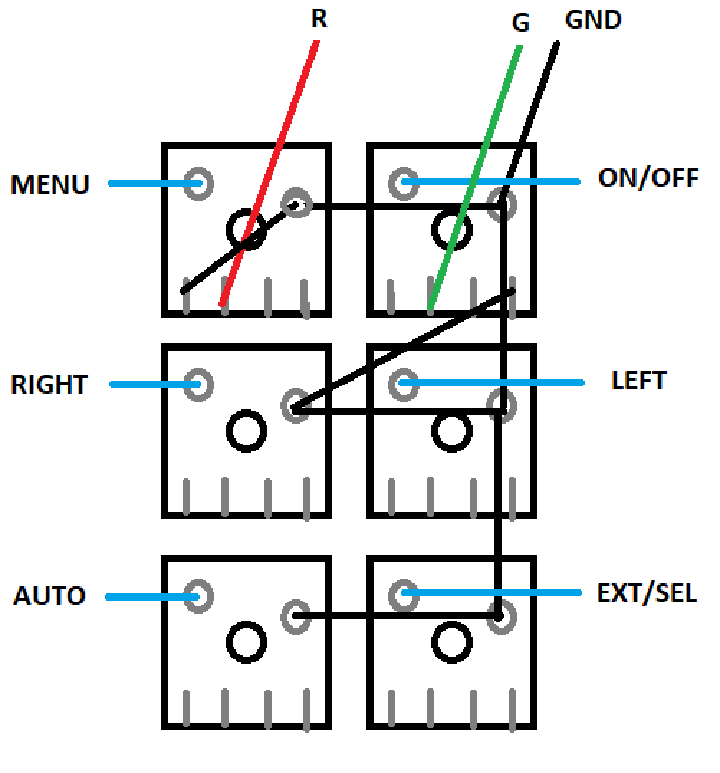
I forgot that I could have used draw.io which was my faithful servant when I studied.. anyways since MS Paint forgot to include a legend for the image:
- Black-colored boxes: MX switches
- Grey-colored lines/circles: solder-able pins
- Blue-colored lines: Keyboard function
- R: Red LED, for when things are not fine
- G: Green LED, for when things are fine
- GND: Ground
- Black lines between grey lines/circles: where to solder to confuse things even more this drawing of the switch footprint is drawn from below. So right key is actually on the left when looking from above. If that makes sense.
The reason why I use two diodes on two different switches instead of one is that - as I previously mentioned the screen panel keyboard RGB is common cathode which is not directly compatible with the mechanical switch RGB which is common anode. Instead of adding extra circuitry, I decided to use two LEDs instead.
Ignoring any thoughts of unnecessary feature creep I can safely say that I am happy with the results. (The green cable is not sticking out in the final version) 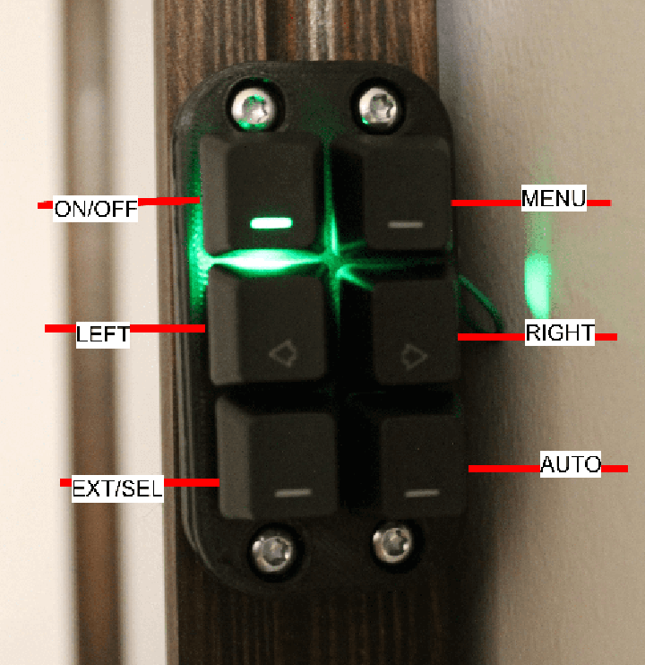
Integrating everything
Now to put everything together. The screen panel is placed directly behind the glass together with a plywood piece with a cutout for the panel. The panel is then fastened using 3D-printed bricks that can be screwed into place in the frame. Then the electronics are installed similarly onto the plywood.
A link to the STLs can be found here..
The LCD panel controller is connected to:
- +12V power supply
- HDMI output from RPI
- Panel keyboard controller which controls the screen (on/off, source selection etc)
- CCFL inverter board which consists of four CCFL inverter circuits that power the screen panel
- Screen panel via its control signal cable
The RPI is connected to:
- +5V power supply
- HDMI output to the LCD panel controller
All this can be seen in the following image: 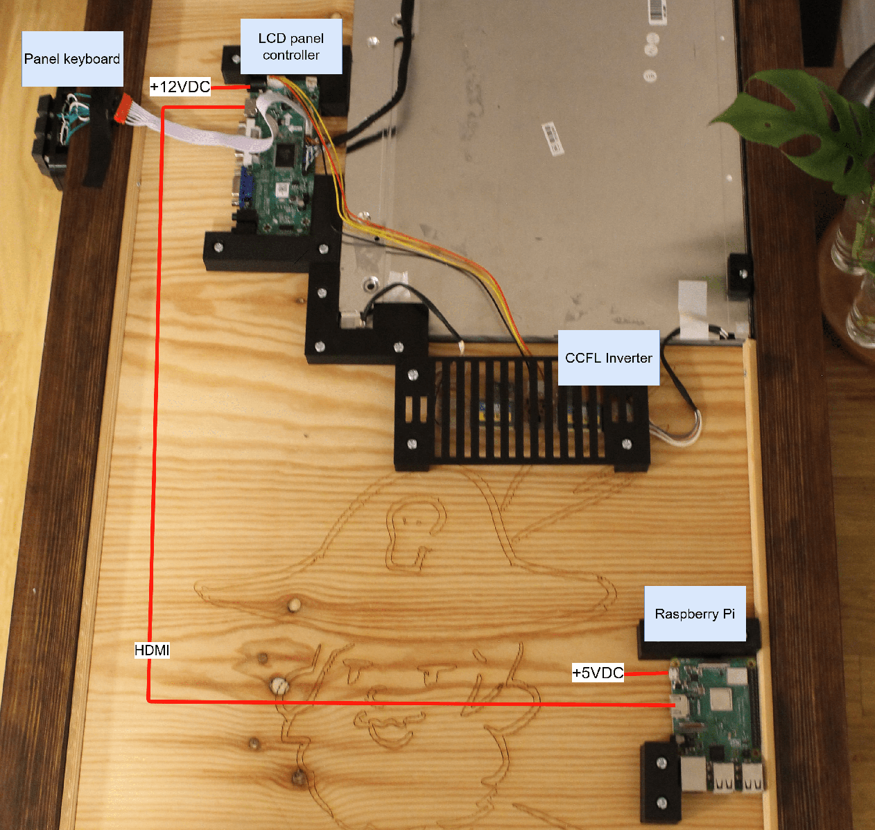
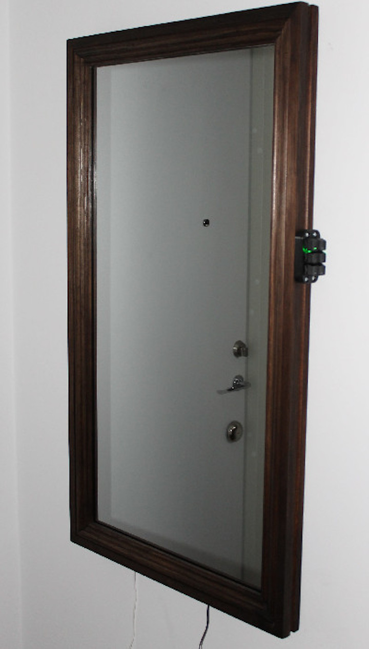
...and finally the mirror on the wall!
Reflections and future improvements
It was both fun and challenging to combine many of my interests into a single project, 3D modeling and printing, woodworking, IoT, which resulted in something that I use almost every day. But am I really done with this project?
This section touches on things I would like to revisit, fine-tune and/or rework.
Cold cathode fluorescent lamps (CCFL)
I can not stress this enough:
Don't use a CCFL screen panel for your smart mirror project:
- Aging: the screen controller or the backlight will break over time. The lifetime of a LED backlit screen is greater.
- Power inefficiency: CCFL backlight is inefficient i.e. draws a lot of power
- Weight and warmth: CCFL screen is heavy and gets warm.
Consider using a LED backlit screen panel/monitor. When my CCFL screen finally dies I will either switch to a LED backlit screen or try to replace the CCFL with LED.
One power cable instead of two
The current solution requires two power cables: one for the screen controller and one for the RPI. The screen panel controller that I bought converts 12VDC to 5VDC for its processing. Instead of having a separate USB power cable to the RPI I could have instead soldered a USB cable to +5V and GND, connect it to the RPI and done with it. The reason I did not do that was that I hastily bought a 12VDC adapter that could output 3 amperes, the exact amount to power the screen but not the RPI. When I can justify buying a second adapter I want to fix this.
An even more lightweight graphical environment
I have read about standalone window managers that do not require a fully-fledged desktop to display GUI-dependent applications. You could argue that LightDM already is a lightweight desktop manager, I mean it is in the name but I am thinking that there should be some specially designed software for this. If there isn't maybe I'll implement my own and write a post about it... if I ever get to it.
Power off the display when no one is home
I want to integrate my smart mirror with Home Assistant. With the help of sensors or geographical data from mobile phones, Home Assistant can determine if someone is home. This information together with some kind of controller circuit for example grounding the ON/OFF panel keyboard pin, I could control whether the screen should be turned on or not. The CCFL screen is, as I've previously stated, power inefficient and with this solution, I could save some kWh every month!